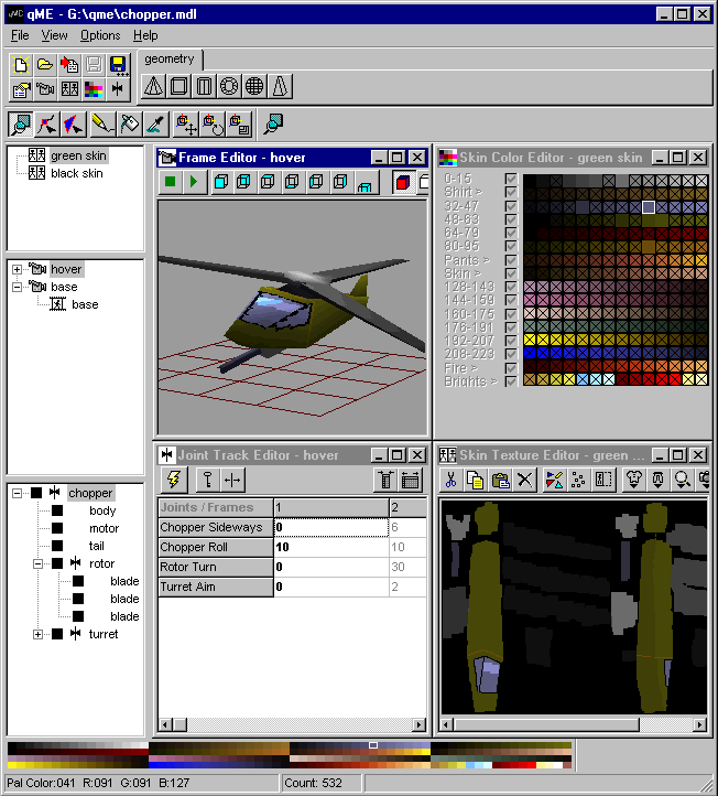
In the main window of qME you find everything you need to load, save and navigate the model.Click inside the screen shot below to find out more about qME's editors, menu's and buttons.
You use the file menu for loading and saving quake model files and for importing and exporting frames and skins.
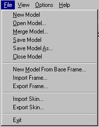
You can select one of the following model operations :
For importing and exporting meshes made in other modeling programs, the following frame operations are supported :
Note that qME expects triangles inside frame files it imports. If qME reports that it cannot find any triangles in your imported file, make sure you have the appropriate export settings selected in your external modeling program. In particular for users of Breeze Designer, make sure you "decompose" the objects before exporting them.
For importing qME currently supports 3D Studio (3DS), LightWave (LWO), Breeze Designer (CAD) and AutoCAD (DXF) formats, for exporting only DXF and CAD are supported.
Just like frames, you also can edit skins in an external graphics editor. For importing and exporting skins, the following operations are supported.
For importing skins qME supports the Windows Bitmap (BMP) and ZSoft Painbrush (PCX) formats. For exporting currently only the BMP format is supported. Note that currently the import of bitmaps is limited to files that have exactly 256 colors. If qME reports a conflicting color depth, then make sure you saved your bitmap with 256 colors.
The view menu is used to start the editors and to show or hide the dockable palettes available in qME.
You can edit the options of all editors and arrange postion of the editors in the main window.
![]()
Use this menu to view the About box.
The top row of the toolbar contains shortcuts to file operations.
![]()
From left to right these buttons represent :
The bottom row of the toolbar containts shortcuts to the editors.
![]()
From left to right these buttons represent :
The object library is a tabbed notebook with buttons that represent prefab models.

Pressing a button will insert the prefab into the current model.
If you want to insert objects from outside the object library, then use the "merge model" operation from the File Menu.
The library is nothing more than a directory tree that is created during installation of qME. The prefab models are normal MDL models that are merged into the model you are building when the button for a prefab is pressed. This gives you the unique capability of creating your own prefabs and use them as basic building blocks in your model creation. Just create sub directories on the same level as the "geometry" directory.
Note that if for some reason the object library disappears, use the "Edit" operation from the Options Menu to select the correct path to the base directory of object library.
The tool palette is used to select an editing tool that can be used in the frame editor or skin texture editor.

A selected tool can be used both in the skin texture editor and frame editor. Look in the respective editor descriptions for the exact description of the tools for that editor.
When an object tool is selected, then objects can be modified even if the frame editor is not open. By selecting an object in the object tree panel and selecting the current frame in the frame tree panel the object pivots can be changed in the Tool Properties palette.
Tool properties let you change the way tools operate. For some tools you can also change values of selected items. Presently, only a few tools have a properties that can be configured, but that may change in future releases.

For the pen tool you can select the pen size to use. The pensize is used both in the Skin Texture Editor and Frame Editor.


Tool properties for object tools operate on the currently selected object. The tool properties for object tools let you configure the range of frames the tool modifies and the way in which it modifies them.
You can change the way an object tool operates in 3 ways:

The scope describes the range of frames on which the movement has impact.

The mode describes how the movement is translated into movement for pivots in frames other than the current frame.
For example when you selected "Relative" mode, and you move an object for example from 10 to 20 in the Z direction, then the pivot in the current frame is at Z=20. The pivots in the other frames that are in the selected scope are all move 10 in the Z direction too.
On the other hand when you selected "Absolute" mode, then when you move the same object from 10 to 20 in the Z direction, then again the pivot in the current frame is at Z=20. But the pivots in the other frames that are in the selected scope are also moved to Z =20 .regardless of their previous position.
![]()
The subject indicates what the object tools should operate on. When you select "Object" as subject, this means that for example moving an object will move the pivot along with the vertices that belong to that object and any child objects.
When "Pivot" is selected as subject, then when you move the object, only the pivot is moved. Neither vertices nor child objects move in this situation.
The skin tree panel contains a list of all skins in the model. Reordering the skins is done by dragging and dropping them in the list. Renaming the skins is done by selecting the skin and then clicking the text. This will put the skin label in edit mode.
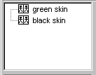
The skin tree panel has a local menu that will appear after selecting and then right clicking a skin. Use this menu to duplicate, create, copy and delete skins from the skin list.
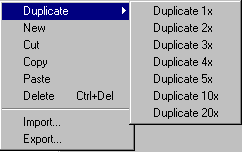
Use the
The frame tree panel contains a hierarchical representation of scenes and frames.
The frames are organized in a two level tree. The root level contains the scenes. A scene depicts an action that a monster can perform like walking, dying etc.
A special kind of scene is the
framegroup. A framegroup can be recognized from the little clock
in the lower left corner of the scene icon ![]() . A framegroup
defines a clientside animation, who's playing is completely
handled outside the Quake C code. In order for a client to be
able to do this, you need to specify the exact duration of every
frame. Look below for a further explanation of client-side
animation.
. A framegroup
defines a clientside animation, who's playing is completely
handled outside the Quake C code. In order for a client to be
able to do this, you need to specify the exact duration of every
frame. Look below for a further explanation of client-side
animation.
You can use drag and drop to reorder scenes, to reorder frames or to move frames between scenes.
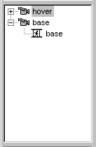
The frame tree panel has a local menu that will appear after selecting and then right clicking a scene or frame. Use this menu to duplicate and delete scenes and frames.
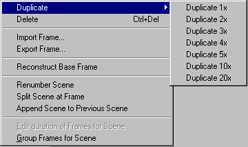
Use the
There are two menu items in this menu that are related to framegroups. As mentioned before framegroups are used for client-side animations. An example of a client-side animations are the torches that you find every where in the Quake levels. These torches are not controlled by game code, but are just frames that are being played in an endless loop.
To create a framegroup use the
"Group Frames for Scene" operation. The scene icon will
change into this ![]() icon. The local menu will be changed too. The
"Group Frames for Scene" menu item is now change into
"Ungroup Frames for Scene" that makes it possible for
you to turn the framegroup back into a regular scene. Also the
"Edit duration of Frames for Scene" menu item will be
enabled when you have selected a framegroup scene.
icon. The local menu will be changed too. The
"Group Frames for Scene" menu item is now change into
"Ungroup Frames for Scene" that makes it possible for
you to turn the framegroup back into a regular scene. Also the
"Edit duration of Frames for Scene" menu item will be
enabled when you have selected a framegroup scene.
Activating the "Edit duration of Frames for Scene" operation will show the following dialog.
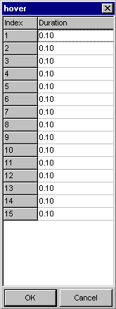
The duration which is specified in seconds can be changed for every frame. The initial duration of each frame is one tenth of a second which means the animation is played at 10 frames per second.
The object tree panel contains a hierarchical representation of objects in the model. There is a single object hierarchy for the whole model.
A pivot holds the state of an object for a single frame. The state consists of a 9 parameters containing a position vector, rotation vector and scale vector of the object.
In every frame an object has a pivot that holds the state of the object in that frame. For example, suppose we have two frames in our model and three objects. We have a pivot for every object in every frame. This means we have a total of 6 pivots in the model.
If you click a solid icon in the hierarchy you will show / hide the object in the frame editor. This only is a view option, that allows you to unclutter your screen. You will not change the model in any way by showing and hiding objects.
For an object you
can designate parameters as a joint. For example you can
designate the rotation around Z as a joint. To start the joint
editor for an object, click a ![]() icon or click on the space where this icon would
appear in the object tree. See the description below for an
explanation of the joint editor.
icon or click on the space where this icon would
appear in the object tree. See the description below for an
explanation of the joint editor.
To change the object hierarchy, drag and drop objects onto each other. Any operation like scaling or moving that are applied to a parent object automatically affect the children of that object too. This is called Forward Kinematics. Future releases may support Inverse Kinematics, which means that operations applied to children will modify the parent objects in order to reach the goal.
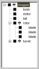
The object tree panel has a local menu will appear after selecting and then right clicking an object.
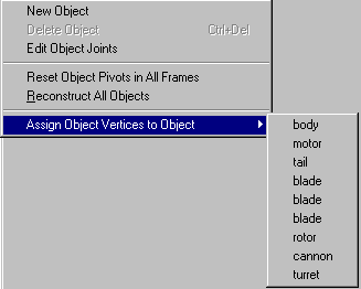
Use the
You can use the joint editor shown below for adding and removing joints.
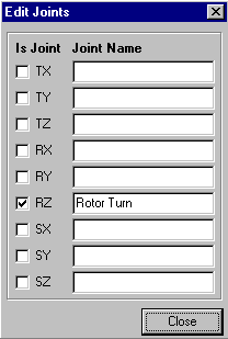
In the image above you see that the Z rotation of an object has been turned into a joint. The name of the joint is Rotor Turn, which will be available as a joint in the Joint Track Editor after closing the dialog.
You can select the color that painting tools should use from this color palette.

The status bar shows information about selections that are made and hints.
![]()
From left to right the the first panel contains specific information about the current selection. The second panel contains infromation about a relevant related item. For example for a vertex the second panel shows the name of the object the vertex belongs to. The third panel shows the current hint.